¬ ®
®
 |
| Figure 6.2: | ETM Sensor Diagram |
|
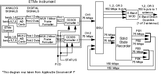
Once the data is scanned, the data from the focal planes are separated into Bands 1-6 and Bands 6,7, and PAN for both multiplexers 1 and 2. Each of the two high speed multiplexers simultaneously output both scene data formats. Only one multiplexer is activated to provide the required ETM+ output data while the other remains in unpowered standby mode as selected by an external node. The Analog/Digital (A/D) converter converts the analog data to digital data which is transferred to the minor frame formatters. The MUX 1 and MUX 2 Minor frame formatters receive format 1 data and format 2 data and formats the data into the minor frame structure. The PCD status words are added and the data is BCH encoded and sent to the CCSDS formatter as format 1 and format 2. Each data stream consists of 8 bits. The CCSDS formatter then transfers the data to the Baseband Switching Unit (BSU) where it will be downlinked to the Landsat ground station or recorded on the SSR to be later downlinked.